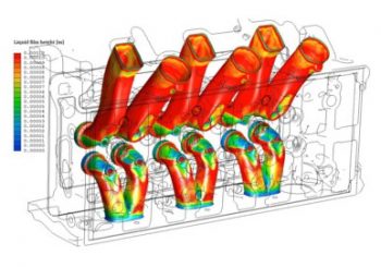
The simulation of metal chip removal with compressed air carried out successfully in 2013 continued in 2014 with new challenges. The results of simulations made in 2013 have been producing profit for the engine manufacturer in every single second of production time since then. In this new phase of the project cleaning performance was further improved. But what kind of new challenges could come after a successfully completed simulation job that led to an optimised cylinder head cleaning process?
The project in 2013 was about reducing the usage of compressed air of a cleaning cell made by an Austrian company. The solution at that time was that all unnecessary movements were eliminated, time of air usage was minimised to just the necessary and nothing more, all of those predicted by CFD simulations. And these movements were proven to be unnecessary because the pilot cell worked pretty fine after movement and air usage optimisation. The article written on the 2013 simulations can be found here, in that I discussed the concept of sliver modeling and determination of necessary cleaning time.
Further energy usage reduction needed
In 2014 the mountain to climb grew even higher.
The already optimised cylinder head cleaning process had to be further improved. The cylinder head – one side of a v6 TDI – remained the same in order to allow proper comparison of simulation results, but all the rest had to go.
The aim in 2014 was to decrease the overall energy consumption of cylinder head cleaning. As an example let’s suppose that before simulations in 2013 that specific cleaning cell required 12kWh energy (in the form of compressed air). After the first simulation set that decreased to 10kWh and the machine ran perfectly well. How can you further improve that?
According to the new way the cleaning cell did not blow air to remove aluminium slivers. It used specially designed and purpose build suction heads and an industrial vacuum cleaner to suck small aluminium particles out of casting channels and cavities.
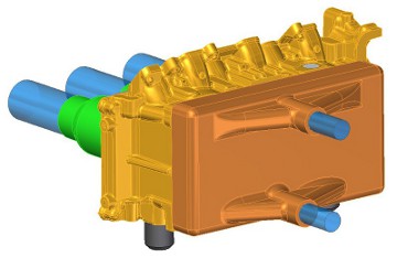
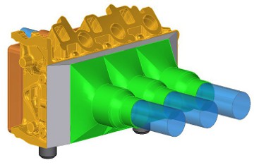
Conceptual design with CFD modelling
Starting from the conceptual design my job was to determine with CFD simulations how suction heads had to look like. Also how long should they be kept at the casting surfaces to remove aluminium chips completely.
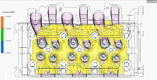
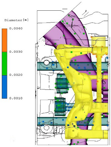
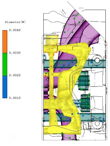
In addition to that how much air a suction head must move? When should it be operated during cleaning process to make the cleaning performance better than it was? We also had to answer some basic questions like which opening of the casting should be used for cleaning? Which one has to remain uncovered to let air in? And so on and so forth.
Long CFD process on many CAD versions
To summarize it: we had to deal with continuously changing CAD models and run CFD simulation on them. Not to mention the fact that each mesh of the simulation had element numbers between 9 to 11 million (that is a lot). Since transient simulations had to be carried out, we had to consider 15 seconds of simulated time.
This does not sound mind-blowingly complicated because anybody can walk for 15 secs but what if one step could only last for 0.001 sec? Translating those to simulation parameters would give us the time step to be 0.001 sec. Such a small value could maintain simulation stability due to expected high air velocity. Keep in mind that the simulation should run for 15 seconds. This leads to 15000 iterations to be done on a 10 million element mesh. And it must be done several times because we are about to develop something and not just analyse a single machine like back in 2013.
So it was very obvious that a lot of calculations were ahead of us. Because of that I had to find a method with SC/Tetra to incorporate changes into the mesh quickly and run the simulation again as fast as possible.
Modular mesh to reduce CFD preparation time
Does modular platform system of the automotive industry sound familiar to you?

This modular platform system means that the basis of a vehicle is formed by putting main sub-assemblies together. Like front part with engine and transmission, middle part with passenger space and the rear part with varieties of suspension types. On this basis different body styles can be designed: 5 door hatchback, 4 door saloon or an SUV.
Since every other method would have been way too time consuming I went for this modular system as well. My modules were the geometries of the suction heads connecting to the surfaces of the cylinder head casting. The main part that remained unchanged throughout the project was the mesh of the cylinder head and its very close surrounding. On each side of the cylinder head that had the slightest chance to attach a suction head to I applied special boundary conditions. We just call it discontinuous mesh in SC/Tetra. This way nodes of the main mesh and nodes of the suction head mesh did not have to have node-to-node connection.
Replacing only those mesh modules that changed
This way I had the flexibility to attach any geometry to the prepared surfaces of the cylinder head main mesh. Of course I used the same element size at both sides of the connecting surface to make sure no problems occur at small details of the geometry. When a geometry change was necessary on one of the suction heads I did this. I just changed the geometry of that specific head, re-meshed it quickly and attached again to the cylinder head. And that was done, the whole mesh was sent to the SC/Tetra solver.
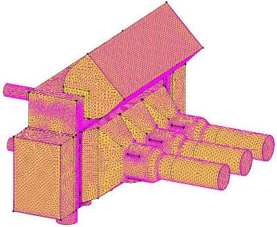
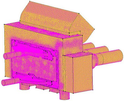
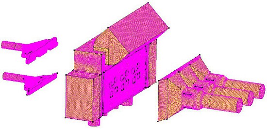
This way we had a flexible system to try several suction head versions with CFD simulations. Comparing results with ones from 2013 we could estimate real life cleaning performance of the new vacuum operated design.
In the next part I will write about the results of comparison and also about a new function of SC/Tetra. I used that function calculate thickness changes of emulsion that covers the internal surfaces of the cylinder head casting.
Click here for Part 2 of the optimised cylinder head cleaning CFD analysis.
Dr. Robert Dul
